Many audio-visual devices only have an RS-232 interface for integrating with a control system. In this article, we’ll provide detailed steps for troubleshooting RS-232 connections, including how to use commonly available terminal programs for sending text-based or hex commands to devices.
While our examples will be focused on the Mira Connect control system, the steps for troubleshooting RS-232 connections are helpful in all applications, whether you are using another control system or simply connecting a computer to a device over RS-232. For more background and best practices when using RS-232, see our previous article about RS-232 best practices.
We’ll assume you followed the best practices (in other words, read the article now if you haven’t already), selected the equipment you want to control in Mira Portal (the cloud-based management platform for Mira Connect), and then connected what you think is the correct RS-232 cable to the actual equipment.
Once you’ve done that, what if you get a ‘Connection failed’ message in Mira Portal, or with other systems, and find that you can’t control the device? What should you do next?
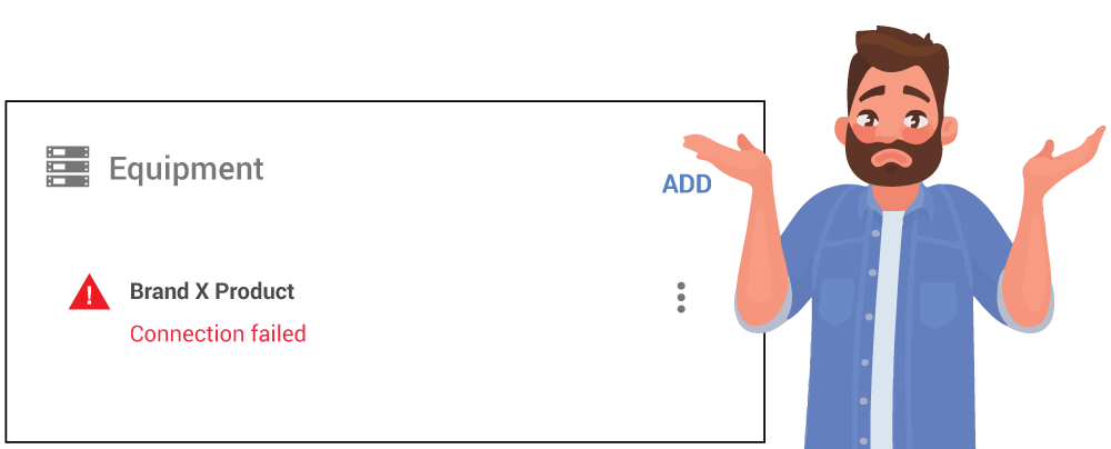
Mira Portal lets you know if Mira Connect isn’t able to communicate to a device.
If you read nothing else, read this section
When RS-232 control of a device doesn’t work, it typically means that somewhere along the path of sending a command to the equipment and receiving a response from the equipment, something is broken or misconfigured. In this article, we’ll show you how to figure it out.
Here is the summary of steps for troubleshooting RS-232 connections that you should follow:
- If using an IP-to-serial interface to connect to the equipment’s serial port over the network and there is more than one IP-to-serial interface in your system, ensure you are working with the correct IP-to-serial device.
-
Ensure the control system has a network route to the IP-to-serial interface. This is the same requirement when communicating between any devices over a network. If the control system can’t reach the equipment over the network, you won’t be able to control it. Also ensure that the IP address of the IP-to-serial interface is unique and not being used by some other equipment on the network. Two devices on the same network with the same IP address is a big problem that should be fixed before any additional troubleshooting steps are taken.
-
Confirm that RS-232 has been enabled on the equipment to control. For example, some displays require navigating their user interface to explicitly enable RS-232 communication. Check your device’s documentation for information about RS-232.
-
Confirm the RS-232 baud rates are the same on the two devices connected over RS-232.
-
Confirm that the serial cable connects the transmit (TX) pin on one device to receive (RX) pin on the other device (and that it also provides a signal ground connection). If you’ve ever heard the phrase “you only need pins 2, 3, and 5,” and nodded your head but didn’t understand, this refers to only needing to connect three pins on each end of the cable – the transmit, receive, and signal ground pins.
-
Optionally, use a terminal program to test whether a device will respond to commands that you send to it. If it does respond, it may indicate an issue with the control system.
If you follow these steps successfully, you’ll be much more efficient while on-site getting the system online and controlling equipment over RS-232.
Note: If your system had been working fine for a while but then stops working (for example, after moving equipment or changing something else in the rack), check that an RS-232 cable has not become unplugged or that your serial cable’s terminations haven’t been compromised. For example, if not properly terminated, a wire can easily get pulled out of a terminal block.
For details about performing each step, please continue reading.
A Little Background First
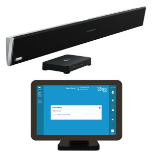
To provide the tools to troubleshoot any RS-232 application, let’s start with a typical system, as shown in the following figure. In this example, the control system sends a command to a device over RS-232 and gets feedback from the device over RS-232. While we show the control system as a Mira Connect, it could be any control system, a computer, or other equipment.

Since Mira Connect controls equipment over a network, an IP-to-serial interface is used to communicate with RS-232-based equipment.
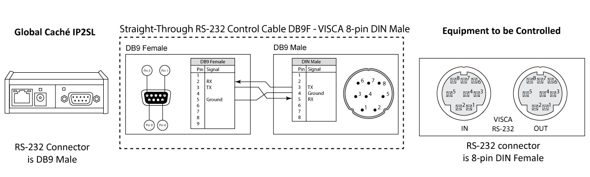
Adding more detail to our system diagram, we see that Mira Connect is connected to a network switch and communicates to the equipment to be controlled through an IP-to-serial interface, such as a Global Caché IP2SL. The IP-to-serial interface converts the network messages to commands sent over RS-232, receives status back from the equipment over RS-232, and forwards it over the network to the control system.

When Mira Connect tries to connect to a device over the network, it opens a communication path, sends a command, and depending on the equipment, expects a response from the device to verify the connection to the equipment.
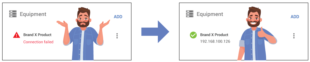
If Mira Connect is unsuccessful in sending a command and receiving an expected acknowledgement, it will show a ‘Connection failed’ message in Mira Portal. When Mira Connect is able to communicate successfully to a device or knows it won’t receive a response (because, unfortunately, some A/V devices never send any messages back), it will show the green circle with the check mark, as shown in the following figure.
When Mira Connect is unable to connect to the device, there are two paths to troubleshoot:
- the network communication path, and
- the serial communication path
Troubleshooting the Network Communication Path
While most issues are found and resolved in the serial part of the system, a few easy network steps to try first are:
- If you are using multiple IP-to-serial interfaces in your system, ensure the device you are troubleshooting is the correct interface.
While this seems obvious, when you have multiple IP-to-serial interfaces in your system, it’s easy to mistakenly spend time working on the wrong device when troubleshooting a complicated system. Confirm the IP address and MAC address of the IP-to-serial interface before spending more time.
- Ensure the IP address of the IP-to-serial interface is reachable by the Mira Connect (or any control system) over the network.
If the IP-to-serial interface is on a different subnet from Mira Connect, then put your computer on the subnet of the Mira Connect and see if you can browse into the IP-to-serial interface at the expected IP address.
See our Global Caché Integration Guide for how to discover and browse into, and configure, Global Caché devices.
If these steps don’t solve the problem, then continue with troubleshooting the serial communication path.
Troubleshooting the Serial Communication Path
There are typically three areas that can prevent successful serial communications:
- Not knowing the baud rate of the equipment to be controlled over RS-232
The baud rate of the equipment to be controlled will be listed in the product’s manual. For many devices, such as VISCA cameras, the default baud rate is 9,600. Baud rates will typically vary from 9,600 to 115,200 bps.
Do not continue past this step until you know the baud rate of the equipment to be controlled.
- The baud rate setting of the IP-to-serial interface is different from the equipment’s baud rate.
The baud rate of the IP-to-serial interface must match the baud rate of the equipment to be controlled over RS-232. Global Caché’s IP2SL interface has a default baud rate of 19,200.
If the equipment requires a baud rate that’s not 19,200, you must change the baud rate on the IP2SL (or change it on the equipment to be controlled). See our Global Caché Integration Guide for information on how to discover the IP address and then set the baud rate on the Global Caché device.
To understand why the baud rates need to be the same, imagine each baud rate is a set of pipes going through a wall. Only when the talker (transmitter) and listener (receiver) are using the same baud rate (or pipe through the wall in this analogy) can they communicate with each other, as illustrated below. Setting the baud rates to the same rate ensures the two devices can listen and talk to each other. Do not continue past this step until you have set the baud rate of the IP-to-serial device to the baud rate of the equipment to be controlled.
- The cable pin-out is not correct
If the control system is still not controlling the equipment once the baud rates are the same, you need to understand the cable pin-out of the controller’s connector, the pin-out of the equipment’s connector, and the pin-out of the cable so that you can ensure that the transmit (TX) pins and receive (RX) pins are connected correctly.
For example, if the cable connects TX to TX and RX to RX, then there’s no communication by either side. The analogy is two people trying to talk through the same pipe and two people trying to listen through another pipe – no communication passes.

Even when the baud rates on both devices are set to the same value, if the cable pin-out isn’t correct (left), the two devices won’t communicate with each other.
Don’t forget to check that the equipment to be controlled is plugged in so that its RS-232 interface is active. Also, some devices only respond to RS-232 commands when they are powered on, or only respond to a power-on command when powered off.
The Serial Cable
Once the baud rate of the IP-to-serial interface matches the baud rate of the equipment, and the device is still not being controlled, then it’s time to troubleshoot the cable and connections. Since the maximum RS-232 cable length is about 50 feet for reliable operation and most A/V installations use significantly shorter RS-232 cables, we’ll assume the cable length (or cable capacitance) is not an issue to troubleshoot in this article.
A serial cable is used to:
- Transmit data (TX) to the equipment and
- Receive data (RX) from the equipment.
To do this, the receive pin on the RS-232 port on the equipment to be controlled must be connected to the transmit pin on the controlling device and the transmit pin on the equipment to be controlled must be connected to the receive pin on the controlling device as shown in the following figure.

There also needs to be a shared signal ground connection between the two devices, providing the transmit and receive signals a common voltage reference.
It’s really that simple for the majority of devices used in A/V installations.
You just need to confirm the transmit pin (TX), the receive pin (RX), and the ground pin (G) on both devices and then connect them, as shown above.
What complicates this task is that the pin-out of the RS-232 connector on the equipment to be controlled, the pin-out of the controller’s RS-232 connector, and the pin-out of the required cable are not always clearly stated in the equipment’s documentation.
What do you do when the documentation is ambiguous? Understand the system and work logically.
Understand the System
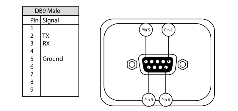
A device with an RS-232 port that uses a male DB9 connector has a male connector with 9-pins as part of the connector. Such a device is often referred to as a DTE — for data terminal equipment device. For example, a Global Caché IP2SL is considered a DTE. DTE devices transmit data on pin 3, receive data on pin 2, and have an electrical ground connected on pin 5.
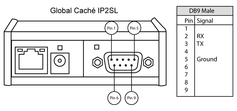
Equipment with a male DB9 connector typically transmits on pin 3 and receives data on pin 2.
Conversely, a device with an RS-232 port that uses a female DB9 socket has 9 sockets as part of the connector. Such a device is often referred to as a DCE — for data communications equipment device. DCE devices receive data on pin 3, transmit data on pin 2, and have a ground connected on pin 5.
Equipment with a female DB9 connector typically transmits on pin 2 and receives data on pin 3.
The naming and pin-outs are a legacy of the days of computer terminals connected to modems where the computer terminal (DTE) used a male connector while the modem (or DCE) used a female connector. The reversal of transmit and receive signals on these two connectors is intentional, allowing a straight-through cable that connects pin 2 to pin 2, pin 3 to pin 3, and pin 5 to pin 5 to connect the two devices.
Note the pin numbering of pins 1-9 of the DB9 female mirrors the numbering of the male connector, so that when the two ends are plugged together, pin 1 connects to pin 1, pin 2 to pin 2, and so on.
You may have heard the phrase “only pins 2, 3, and 5 are required” for a particular device. These pins correspond to the transmit, receive, and ground pins on a DB9 connector. For essentially all A/V installations, connecting the TX, RX, and ground are all you’ll ever need.
For this article, we’ll ignore the other 6 pins (used for flow control signalling, etc.), since most A/V devices with RS-232 ports only require the TX, RX, and signal ground to be connected for successful communication. If you want to learn more about RS-232 communications and the electrical signaling aspect, here’s an interesting article from Analog Devices.
In our example, we would use a straight-through cable to connect the two devices together, as shown in the following figure.

Checking Continuity of the Serial Cable
Now that you know that the cable’s sole purpose is to connect the TX pin of one device to the RX pin of the other device, and vice versa, you can easily troubleshoot what’s not working correctly.
If you are unsure if your cable is a straight-through cable (or suspect your cable may have an open or short circuit due to soldering or a manufacturing defect), you can confirm the cable’s pin-out with a multimeter tool. Using a multimeter, set the dial to 200 Ω resistance (or the smallest resistance value on the multimeter) and measure whether pin 2 is wired to pin 2, pin 3 is wired to pin 3, and pin 5 is wired to pin 5.
Since the serial cable has some length to it and has small diameter wires, there will be some resistance measured even when the pins on the ends of the cable are connected as expected, but the resistance will be much less than 100 Ω. If the pins on the ends of the cable are wired properly, you will see the small resistance value measured between the two pins. If the pins are not connected, the multimeter will show an ‘out of range’ or high value.
Even if you’ve purchased a pre-made cable, it’s important to confirm the pins are connected as expected.
If your multimeter’s probe doesn’t fit into the DB9 female socket, you can use a paperclip or a strand of network cable (with the insulating cover stripped back about 1/4 inch) pressed against the probe and pressed into the RS-232 socket.
Remember the pin numbering on male and female DB-9 connectors are mirror images of each other so that when they are plugged in together, pin 1 maps to pin 1, etc. Checking whether pin 2 is connected to pin 2 will require checking pin 2 on both connectors, as shown in the following figure.
As a best practice, write down which pins are connected to each other so you can keep track of which pins you’ve checked and document the cable in your system drawings.
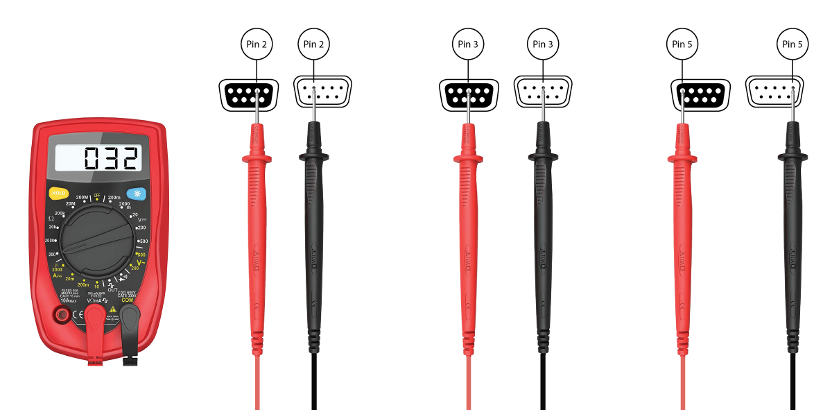
Using a multimeter allows you to check continuity between pins 2 to 2, 3 to 3, and 5 to 5 to confirm a straight-through cable.
While this example showed the RS-232 interface on the equipment to be controlled as a DB-9 female connection, you’ll find a variety of connectors in the field as shown in the following figure.

RS-232 connectors can have many different forms depending on the manufacturer. All of these connectors have designated TX, RX, and ground pins. Beware that not all terminal block connectors use the same pin-out!
VISCA cameras, for instance, will typically have an 8-pin min-DIN connector, as shown below.
Regardless of the connector type and pin arrangement, you should follow the same steps described in this article to ensure the TX pin on one device is connected to the RX pin on the other device and the RX pin on one device is connected to the TX pin on the other device.
Using a Null Modem Adapter to Check if TX and RX are Reversed
 If you’ve confirmed the pin-out for the cable based on the equipment’s documentation and you are still not communicating to the device successfully, it could be that the pins on the equipment are reversed from the documentation. Try reversing the RX and TX connections by using a null modem adapter (or simply reverse the TX and RX on one-end of the cable, if that’s easier).
A null modem is a small connector that provides a cross-over between TX and RX so pins 2 and 3 are reversed as shown in the following figure.
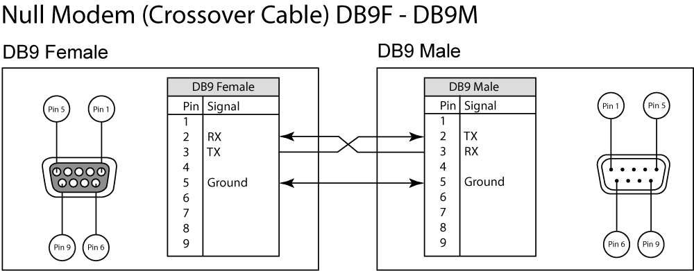
A null modem will convert a straight-through cable into a cross-over cable and also will turn a cross-over cable into a straight-through cable (due to ‘double’ crossing). Null modem adapters are handy to have in your tool bag.
Sending Commands Manually
If your serial cables are wired correctly, but the control system is still not connecting to the equipment, you can try to connect your computer directly to the equipment (without the control system) and see if you can send commands to the device and get responses. This lets you determine whether the control system has an issue or whether you need to continue troubleshooting the system.
Note: Before sending commands manually to a device, check if you have added the device into your room in Mira Portal, and Mira Connect is trying to control the device. To prevent Mira Connect from interfering with your manual communications, edit the device in Mira Portal, choose ‘Simulate equipment’ and then click ‘UPDATE EQUIPMENT.’ This will keep Mira Connect from trying to send commands at the same time you are working manually to send commands.
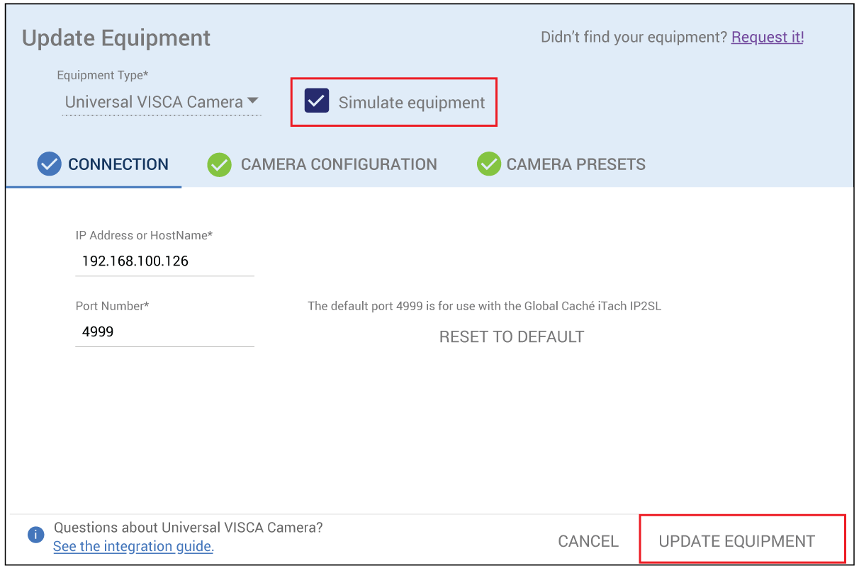
Choose ‘Simulate equipment’ and click ‘UPDATE EQUIPMENT’ to prevent Mira Connect from trying to send commands to the device.
As described next, open your favorite terminal program, connect directly over RS-232 or through the IP-to-serial interface, and send commands to the equipment to be controlled.
Using the PuTTY Terminal Program
PuTTY is a well-known computer terminal program for communicating with equipment over a network connection or an RS-232 connection. PuTTY is easily downloaded and installed on a Windows-based computer.
If you’re comfortable using a terminal program like PuTTY, you can send text-based commands from your computer’s serial port directly to the device or connect to the device to be controlled through an IP-to-serial interface.
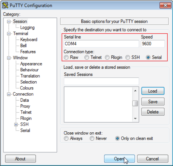
To use your computer’s serial port directly, run Device Manager on a Windows computer and determine which COM port is available as shown in the following figure. In this case, COM4 is mapped to a USB-to-serial interface that is plugged into the computer.

Next, run PuTTY, select the ‘Serial’ connection type and enter the COM port to be used (COM4 in this example). Then click ‘Open’ to open the terminal.
If you don’t have a serial port or USB-to-serial interface on your computer, you can also connect directly to an IP-to-serial interface at its IP address and port 4999 (as shown below) and click ‘Open.’ Here we’ve assumed the IP address of the IP-to-serial interface is 192.168.100.123. The port used for the Global Caché IP2SL is typically 4999.

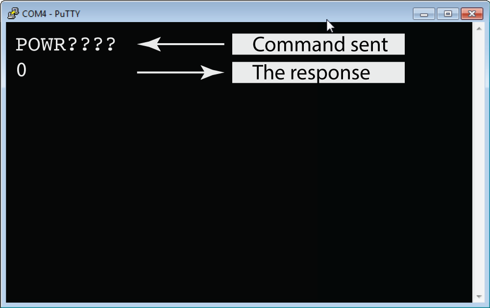
Once the terminal window is open, enter a command to send to the device.
Note: Many, but not all, devices to be controlled accept a carriage return (or pressing ‘Enter’ on your keyboard) to terminate the command. A command terminator informs the equipment to be controlled that the command is complete and should be processed. Check the product’s documentation if you’re unsure of the command syntax or the proper termination for commands.
In this example, we’ve sent a power query specific to a Sharp Aquos display by typing POWR???? and then pressing ‘Enter’ on the keyboard to terminate the command. If the Sharp display is connected properly, the current power status will be received from the display. In this example ‘0’ was returned indicating that power is turned off.
Sending manual commands tells you that there is a valid connection between your PC’s serial port (or through the IP-to-serial interface) and the device to be controlled. Next steps would be to:
- Close the terminal program (so you don’t have an extra communication path still connected);
- Connect the serial cable back to the IP-to-serial interface; and
- Uncheck the ‘Simulate equipment’ box in Mira Portal and click ‘UPDATE EQUIPMENT’ so Mira Connect can connect to the equipment.
Using the RealTerm Program for Binary/Hex Commands
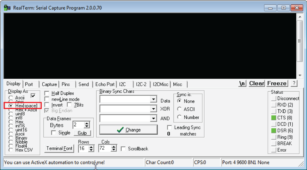
If the equipment to be controlled requires sending binary/hexadecimal values to control it (such as a VISCA camera or a Philips display), try a different terminal program, such as RealTerm. While PuTTY is a great tool for text-based commands, it doesn’t readily support sending binary or hex commands to a device. Instead, we’ll show an example using RealTerm for sending a power query to a VISCA camera using COM4 at 9600 baud.
After installing the RealTerm software on a Windows PC, navigate to the ‘Display’ tab and set the RealTerm display mode to ‘Hex’ to view the responses coming back from the camera as hex values.
Then navigate to the ‘Port’ tab and set the baud rate to 9600, select COM4 (that’s where the USB-to-serial interface is mapped, as described previously) and click ‘Open’ to open the port.

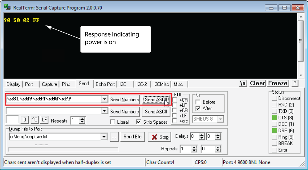
Finally, on the ‘Send’ tab, enter the power query command for a VISCA camera at ID = 1 (\x81\x09\x04\x00\xFF) and click ‘Send ASCII.’ The values \x81\x09\x04\x00\xFF correspond to binary values represented as hexadecimal digits. You will see the TXD and RXD lights flash on Status control shown on the right of this tab when you successfully send and receive commands. When powered off, some VISCA cameras only respond to a power-on command. If your camera is powered off, you can try to send the power-on command \x81\x01\x04\x00\x02\xFF and see if it powers on the camera.
A response to the power query from the camera of 90 50 02 FF means that we are communicating with the VISCA camera and that the camera is powered on (02 means power is on; 03 means power is off).
Manually sending commands (hex/binary commands in this example) and getting responses confirms the correct pin-out on the cable, indicating that you should be able to successfully control the device.
After successfully sending commands manually to the equipment, the next steps are to
- Edit the device in Mira Portal;
- Uncheck the ‘Simulate equipment’ box;
- Click ‘UPDATE EQUIPMENT’ and see if Mira Connect can successfully connect to the equipment.

If you’ve followed these steps and have set the baud rates correctly, have the correct IP address and port number for your device, and have a cable with TX connected to RX and vice versa, then you should see Mira Portal indicate a successful connection.

If you still can’t control the device, please review the steps outlined above and see what was missed along the way. Remember that devices need to be plugged in for their serial ports to work!
Summary
Serial connections are still often used to control devices, and with an IP-to-serial interface, you can control these devices over a network. Ensure that you match the baud rate on the IP-to-serial interface and the equipment to control and that your cable is pinned out correctly (TX on one device connects to RX on the other device), and you’ll save yourself a lot of time on site.
Don’t forget to try the easy network troubleshooting steps to make sure you’re working with the expected IP-to-serial device and that the control system has a network route to the IP-to-serial device.
With some background knowledge and troubleshooting steps, serial communication can be (and should be) easier to get working than network communications. Since it’s a low-speed communication path directly between two devices, there are only a few steps required to make it work successfully. Armed with these steps, you will be successful when you’re troubleshooting RS-232 connections.
For more information about Mira Connect, visit https://aveosystems.com.